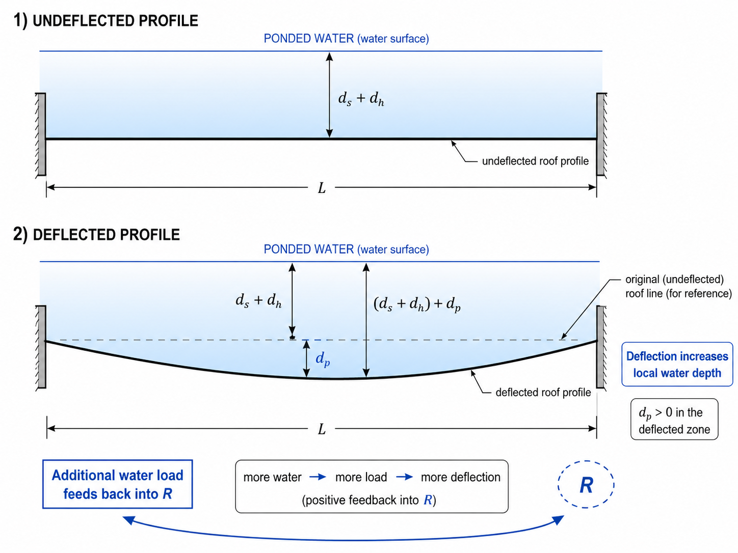
Rain load under ASCE 7 is the weight of the water that collects on a roof when the primary drains are blocked. ASCE 7-10 and 7-16 compute it as ; ASCE 7-22 adds a third term, . Static head is the depth up to the inlet of the secondary drainage that still works. Hydraulic head is the extra depth needed to push the design flow through that inlet. Ponding head is the extra depth that collects because the roof deflects. The work is in three places: deciding which secondary system counts, reading for the actual drain geometry, and computing on flexible framing. This article walks through each and calls out where the edition changes the answer.
Rain loads are also easy to skip. FM Global's loss data from 2007 to 2017 found that rain-related structural losses occurred 50% more often than snow-related losses, and rain losses in Texas and Arizona roughly equaled snow losses in New England.[1] A survey at a large Northeast engineering firm found that most respondents did not routinely calculate rain loads in heavy-snow regions and relied on snow load to bound the design.[1] (If you do need that number, our free snow load calculator computes balanced flat and sloped roof snow loads across ASCE 7-10, 7-16, and 7-22.) ASCE 7 doesn't support that shortcut. ASCE 7-10 and 7-16 Section 8.3 and ASCE 7-22 Section 8.2 require each portion of the roof to carry the rain that accumulates with the primary drains blocked, whatever the snow load is.[2,3,4]
Not every jurisdiction has adopted ASCE 7-22. Confirm the governing edition first, because it decides whether is in the equation at all.
The Rain Load Equation Across Editions
ASCE 7-10 Section 8.3 and ASCE 7-16 Equation 8.3-1 give the design rain load as:[3,4]
where:
- = rain load on the undeflected roof (lb/ft²)
- = static head (in.)
- = hydraulic head (in.)
The 5.2 is a unit conversion, not a safety factor: water weighs 62.4 lb/ft³, and per inch of depth.
ASCE 7-22 adds ponding head:[2]
where is the depth of water due to roof deflection under unfactored rain load and unfactored dead load (in.). The other terms are unchanged.
In ASCE 7-16, ponding was a separate check (Section 8.4): susceptible bays needed enough stiffness to prevent progressive deflection and enough strength for the added ponding load, but that load was not part of . ASCE 7-22 Commentary C8.2 explains the change:[2]
"The definition of rain load was changed in the 2022 edition of the standard to include the additional load due to ponding. This eliminates the need to perform a separate ponding instability check, however, the effects of ponding need to be explicitly included in the rain load."
The Commentary's own worked example shows the size of the change. For a steel bay with 40-ft W24×76 girders, 40-ft W18×35 beams, and in., the ponding amplification factor is , and rises from 26 psf to 44 psf.[2] The worked example below reproduces that calculation with real drain inputs.
Edition note: appears only in ASCE 7-22 Eq. 8.2-1.[2] Projects governed by ASCE 7-16 or ASCE 7-10 use , with ponding instability checked separately under ASCE 7-16 Section 8.4[3] or ASCE 7-10 Section 8.4.[4] AISC 360-2022 removed Appendix 2 (ponding); for structural steel, the current ponding reference is AISC/SJI Design Guide 40 (2024).[5]
Step-by-Step: Calculating R
Step 1 — Identify the Qualifying Secondary Drainage System
Every term after this depends on which drainage system is assumed to still be working, so this step comes first. It is also the step where the three editions differ most.
ASCE 7-10 required separate drain lines for secondary systems (Section 8.3) and a secondary system at a higher elevation on roofs with controlled drainage (Section 8.5).[4] It did not define "secondary drainage system." What counted was engineering judgment.
ASCE 7-16 added definitions, including PRIMARY DRAINAGE SYSTEM, SECONDARY DRAINAGE SYSTEM, and SUSCEPTIBLE BAY. It also set the secondary design storm at 15-min/100-yr (Section 8.2), required the total head to be based on hydraulic test data (Section 8.3), and prohibited controlled flow roof drains on the secondary system (Section 8.5).[3] It still did not say when a system labeled "secondary" should be ignored for structural loading.
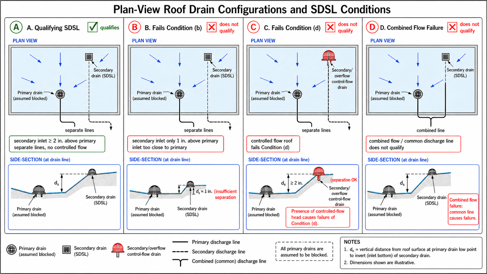
ASCE 7-22 answers that question. Section 8.2 assumes that any drainage system meeting one of these four conditions is blocked:[2]
(a) The primary drainage system.
(b) Secondary drainage systems with an inlet vertically separated from the primary inlet by less than 2 in. (51 mm).
(c) Secondary drainage systems that share drain lines with the primary drainage system.
(d) Secondary drainage systems with controlled flow roof drains.
The system that remains is the Secondary Drainage System for Structural Loading (SDSL), a term new in ASCE 7-22. Its inlet elevation sets . If the drain the plumbing engineer designated as secondary meets any of (b)–(d), it is assumed blocked, and the next point of discharge becomes the SDSL. One exception from Commentary C8.2: when the primary drainage is a free-draining roof edge, that edge can also serve as the SDSL, because an edge can't clog.[2]
So a label on the plumbing drawings no longer settles the question. ASCE 7-22 Commentary C8.2 says so directly:[2]
"It is possible that a drainage system that is designated as a secondary or emergency overflow drain, by the architect or mechanical (plumbing) engineer, is required to be assumed to be blocked, per Section 8.2. Such a drainage system cannot serve as the SDSL."
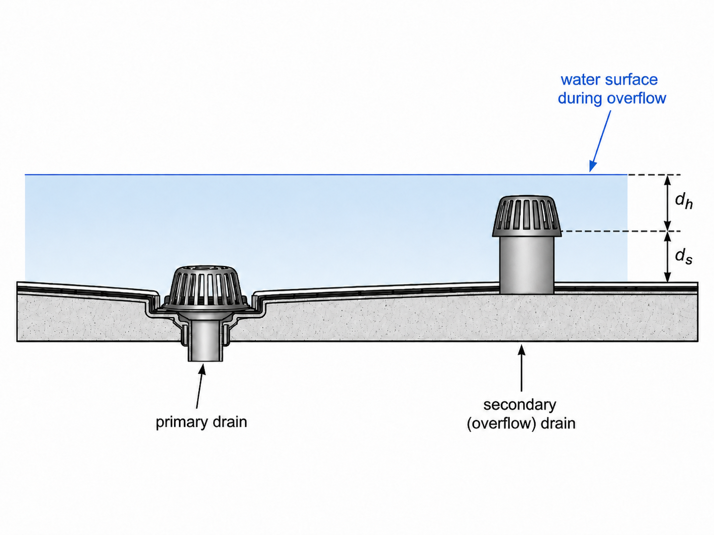
Section at the drains. Vertical scale exaggerated; parapet 6 in. Tap or hover i for what each part is and why it matters.
ASCE 7-22 Section 8.2 screen
Plumbing drawings call it: secondary (overflow) drain
The overflow standpipe is the SDSL.
dₛ = 3.0 in. → 5.2 × 3.0 = 15.6 psf static head.
Add dₕ (Step 3) and, under ASCE 7-22, dₚ (Step 4).
Controlled flow drains are the case to watch. Where local ordinances limit stormwater release rates, controlled flow drains are common on the primary system, and Condition (a) already treats the primary as blocked. The problem is a secondary system that also uses controlled flow drains, or no qualifying secondary system at all. Condition (d) assumes it is blocked and the SDSL moves to the next point of discharge. Commentary C8.2 names the extreme case: with no qualifying overflow drainage, flow over the parapet becomes the SDSL.[2] With a 6-in. parapet, in. instead of 3.0 in. for a typical overflow standpipe, which adds psf before or . The Commentary's remedy is design team coordination, and it only works if it happens before the drainage plan is final.
On roofs with several bays that differ in tributary area, drain type, or inlet elevation, make the SDSL determination bay by bay.
Prose's rain module evaluates each bay independently. You define the drain configuration for each bay: drain type, standpipe or scupper size, inlet elevation relative to the primary, and whether controlled flow is in play. Prose runs the ASCE 7-22 Section 8.2 conditions against each one, sets at the SDSL for that bay, and carries the result into the full calculation. The report documents each bay's SDSL determination separately and cites the governing section.
Step 2 — Determine Static Head ()
ASCE 7-22 Section 8.1.2 defines static head as the depth of water on the undeflected roof up to the SDSL inlet.[2] For an overflow drain, that is the height of the dam or standpipe above the roof surface (ASCE 7-22 Commentary Table C8.2-1, Note 2). For a scupper, it is the height of the scupper invert, the bottom of the opening, above the roof surface. Take it from the drain detail.
Watch the datum. Condition (b) measures the 2-in. separation from the primary inlet, but is measured from the roof surface.
Step 3 — Determine Hydraulic Head ()
Hydraulic head is the water depth above the SDSL inlet needed to pass the design flow. It depends on drain type, size, and flow rate. The flow through a single drainage system is (ASCE 7-22 Commentary Eq. C8.2-1[2]):
where:
- = flow rate out of a single drainage system (gal/min)
- = tributary roof area served by that drain outlet, plus one-half the area of any wall that diverts rainwater onto the roof (ft²)
- = design rainfall intensity for the 15-minute duration storm (in/hr)[6]
Take the 15-minute intensity at the return period from ASCE 7-22 Table 8.2-1. The ASCE 7 Hazard Tool reports rainfall intensity by location,[7] and ASCE 7-22 Commentary C8.2 points to the NOAA Precipitation Frequency Data Server for the same data. If the source gives a 15-minute depth, multiply by 4 to get in/hr.
Use the 15-minute storm, not the 60-minute storm used for plumbing design. The International Plumbing Code sizes both primary and secondary drains for the 60-min/100-yr event (ASCE 7-22 Commentary C8.2), so flow data from the plumbing design may carry the longer duration.[2] The 15-minute intensity is roughly twice the 60-minute intensity for most U.S. locations,[8,9] so roughly doubles. For the 6-in. overflow standpipe in Table C8.2-1, going from 100 to 200 gal/min raises from 1.5 in. to 2.5 in., or 5.2 psf.
Edition note: ASCE 7-22 Table 8.2-1 sets the design storm return period by Risk Category: 100 years for I and II, 200 years for III, and 500 years for IV.[2] ASCE 7-16 Section 8.2 uses a 100-year return period regardless of Risk Category: the 15-minute storm for the secondary system and the 60-minute storm for the primary.[3] ASCE 7-10 Section 8.2 specifies no design storm; it requires only that secondary drains have at least the flow capacity of the primary drains.[4]
With in hand, read from the ASCE 7-22 Commentary tables: C8.2-1 and C8.2-2 for overflow dam and standpipe drains, C8.2-3 and C8.2-4 for rectangular scuppers, and C8.2-5 and C8.2-6 for circular scuppers. ASCE 7-16 has the same set, numbered C8.3-1 through C8.3-6. The drain and rectangular scupper tables are adapted from FM Global test data;[10] the circular scupper tables come from Carter (1957) and Bodhaine (1968).[2] ASCE 7-22 Section 8.2 allows either hydraulic test data or hydraulic calculations, so the tables are one route, but the one most engineers will take.
Don't assume in. That single value came from ASCE 7-93 and was removed because varies too much with drain type.[2] At 300 gal/min, Table C8.2-1 gives 1.5 in. for a 17-in. dam on a 10-in. outlet and 3.0 in. for a 6-in. standpipe, 7.8 psf apart for the same flow. The table notes permit linear interpolation for approximations and prohibit extrapolation. Where the specified dam or standpipe diameter differs from the tested one, Commentary Eq. C8.2-3 adjusts ; the Commentary advises staying at or above 80% of the tabulated value unless flow test results justify less.
Step 4 — Determine Ponding Head () — ASCE 7-22 Only
Ponding head comes from structural analysis under unfactored dead load plus unfactored rain load. ASCE 7-22 Commentary C8.2 accepts four methods: iterative analysis, springs with negative stiffness, closed-form solutions for simple cases, and amplified first-order analysis.[2] For rectangular bays with primary members supporting equally spaced secondary members, the amplified first-order method (Denavit 2019[11]) is the most practical by hand:
where, in any consistent units:
- = unit weight of water (62.4 lb/ft³)
- = primary member span
- = secondary member span
- = secondary member spacing
- , = flexural rigidity of the primary and secondary members. If an open-web joist or truss is modeled as a beam without shear deformation, Commentary C8.2 notes it is common to reduce the moment of inertia by 15% to account for it.[2]
multiplies the first-order total load, dead load plus rain load with . With , the rain load is . As approaches 1, grows without bound; at 1 or above, the bay is ponding-unstable and needs stiffer framing.
Both flexibility coefficients scale with span to the fourth power. Short, stiff framing gives close to 1 and a negligible . Long-span steel is where gets large.
Worked Example
Commercial building in Raleigh, NC, Risk Category II. Roof framing: W24×76 girders spanning 40 ft, supporting W18×35 beams spanning 40 ft at 8-ft spacing. Dead load 15 psf. Secondary drainage: 6-in. overflow standpipe on a 4-in. outlet, inlet 3.0 in. above the roof surface, primary inlet flush with the roof, separate drain lines, no controlled flow. It meets none of Conditions (a)–(d), so it is the SDSL under ASCE 7-22 Section 8.2.[2] Tributary area per drain: 2,500 ft², with no walls shedding onto the roof.
The framing and the , , and values match the worked example in ASCE 7-22 Commentary C8.2.[2] On a project, compute and from the actual member properties.
Given:
- Location: Raleigh, NC; Risk Category II → 15-min/100-yr storm (ASCE 7-22 Table 8.2-1[2])
- Rainfall intensity: (ASCE 7 Hazard Tool[7], 15-min, 100-yr)
- Tributary area:
- SDSL: 6-in. overflow standpipe, 4-in. outlet, inlet 3.0 in. above the roof surface
- Dead load:
- Primary framing: W24×76, →
- Secondary framing: W18×35, , →
Step 1: Design flow rate — ASCE 7-22 Commentary Eq. C8.2-1[2]
Step 2: Static head — ASCE 7-22 Section 8.1.2[2]
Step 3: Hydraulic head — ASCE 7-22 Commentary Table C8.2-1[2]
The 6-in. standpipe column lists 1.5 in. at 100 gal/min and 2.5 in. at 175 gal/min. Taking the next tabulated flow above 157.6 gal/min gives 2.5 in. Linear interpolation, which the table notes permit for approximations, gives 2.3 in. This example uses 2.5 in.
Step 4: First-order rain load — ASCE 7-22 Eq. 8.2-1 with [2]
Step 5: Ponding amplification factor — ASCE 7-22 Commentary Eq. C8.2-4[2]
Step 6: Amplified total load and rain load
Step 7: Factored strength demand — ASCE 7-22 Section 2.3.1 (LRFD)[2]
Result: , ,
Without ponding (the two-term equation): . Ponding raises the rain load on this bay by 67%.
The two-term equation gives 28.6 psf on this bay. That reads as an ordinary rain load, so nothing in the load summary flags the missing 19.2 psf. It only surfaces if someone checks whether was computed.
What a complete rain loads report looks like in practice. A 20,000 sf single-story commercial building might have three or four drainage zones: interior bays with overflow dam drains, perimeter scuppers at a lower parapet, and one bay whose only secondary drain has a controlled flow head, which pushes that bay's to the parapet overflow height. Each zone is a separate calculation with its own , , , and . Prose runs all of them. It takes the drain type and size for each bay, pulls the rainfall intensity from the ASCE Hazard Tool, looks up from the Commentary tables for that drain geometry, computes from the roof framing, and outputs each bay as a separate, code-referenced calculation. Every bay is documented, every variable is traced to its governing section, and the SDSL determination is explicit for each drainage zone.
Low-Slope Bays Without Accumulated Rain: ASCE 7-22 Section 8.3
Bays that don't impound water under Section 8.2, such as free-draining bays and internal bays, still need enough strength and stiffness to resist ponding under ASCE 7-22 Section 8.3 when either condition applies:[2]
- The roof slope is less than 1/4 in/ft (1.19°), or
- The bay is adjacent to a free-draining edge with secondary members parallel to that edge, and the roof slope is less than :
where is in in/ft, and (secondary member span) and (secondary member spacing) are in the same units.
Take the same framing in a bay adjacent to a free-draining edge, with the secondary members parallel to that edge:
A roof sloped at 3/8 in/ft is steeper than 1/4 in/ft, so Condition 1 does not apply. It is flatter than 0.41 in/ft, so Condition 2 does, and the bay needs a ponding investigation under ASCE 7-22 Section 8.3.
For secondary members perpendicular to the free-draining edge, ASCE 7-22 Commentary C8.3 derives the equivalent limit:[2]
For :
That is below 1/4 in/ft, so Condition 1 covers this geometry. It stops covering it once exceeds about 1.86, where the Commentary value passes 1/4 in/ft; Section 8.3 still only requires the 1/4 in/ft check for perpendicular framing. For those bays, checking against the Commentary value is the more conservative choice. For interior bays, the Commentary derives in/ft, and Section 8.3 specifies 1/4 in/ft.
Edition note: ASCE 7-16 Section 8.4 defined four "susceptible bay" conditions: (1) slope < 1/4 in/ft with secondary members perpendicular to the free-draining edge; (2) slope < 1 in/ft with parallel secondary members; (3) slope equal to 1 in/ft with parallel secondary members and a span-to-spacing ratio > 16; and (4) bays where water accumulates when the primary drains are blocked but the secondary system works.[3] ASCE 7-10 Section 8.4 had two: slope < 1/4 in/ft, or water impounded when the primary drains are blocked.[4] ASCE 7-10 did not require checking the parallel-member configurations, which IIBEC identifies as carrying higher ponding collapse risk than perpendicular framing.[9] Both ASCE 7-10 and 7-16 Section 8.4 use the larger of the snow load and the blocked-primary rain load in the ponding analysis. ASCE 7-22 moves snow ponding to Section 7.11, which requires evaluating roof deflection under full snow load.[3,4,2]
Drainage onto Existing Roofs: ASCE 7-22 Section 8.4
ASCE 7-22 Section 8.4 prohibits drainage from new construction onto an existing roof unless the existing roof is evaluated and either carries the Chapter 8 loads or is upgraded to.[2] Commentary C8.4 cites existing roofs that failed after alterations, additions, or new construction increased the rain load on them, often on roofs designed to older codes that did not require secondary drainage.[2] The added flow does not have to come from a downspout: a new wall built directly beside an existing roof can shed sheet flow onto it. On an addition, trace where the new drainage and wall runoff end up. If either reaches an existing roof, Section 8.4 applies.
The Bottom Line
Confirm the governing edition first, because it decides whether is in the equation. Then, for each bay: run the drainage systems through ASCE 7-22 Section 8.2 Conditions (a)–(d) to find the SDSL; take from its inlet height above the roof surface; compute from the 15-minute intensity at the Table 8.2-1 return period, including half of any wall area that sheds onto the roof; read from the Commentary table for the actual drain geometry; and on 7-22, compute from the framing. Check the bays that don't impound water against Section 8.3, and trace any new drainage that lands on an existing roof. If you want that documentation handled automatically — SDSL per bay, all three editions, // per drainage zone, code-referenced throughout — that's what Prose is built to do.
Frequently Asked Questions
How do you calculate rain load per ASCE 7?
What changed in rain loads from ASCE 7-16 to ASCE 7-22?
What is the difference between static head and hydraulic head?
What is ponding head (d_p) and when is it required?
What qualifies as the Secondary Drainage System for Structural Loading (SDSL)?
How do controlled flow drains and scuppers affect rain load?
Can snow load be used in place of rain load?
Related Resources
- ASCE 7-22 Snow Load Changes — the parallel edition-basis shifts in Chapter 7, including rain-on-snow and the snow-vs-rain ponding interaction
- Replace your rain load spreadsheets — why edition-specific load development belongs in a tool that cites its own work
If you read this provision differently or have run into it applied another way on a real project, reach out — support@prose-eng.com. I'm a practicing engineer, not an infallible one.
See a real loads package, fully cited
Wind, snow, seismic, rain — generated across ASCE 7-10/16/22 with every step traced to code.
Review a sample reportReferences
- Van Durme, R.(2021). “Do Structural Engineers Design for Rain Loads?.” Structure Magazine. https://www.structuremag.org/article/do-structural-engineers-design-for-rain-loads/ FM Global loss data 2007-2017; profession-wide survey on rain load under-application.
- American Society of Civil Engineers. Minimum Design Loads and Associated Criteria for Buildings and Other Structures(ASCE/SEI 7-22), Selected provisions and commentary. Reston, VA:ASCE, 2022.
- American Society of Civil Engineers. Minimum Design Loads and Associated Criteria for Buildings and Other Structures(ASCE/SEI 7-16), Selected provisions and commentary. Reston, VA:ASCE, 2016.
- American Society of Civil Engineers. Minimum Design Loads and Associated Criteria for Buildings and Other Structures(ASCE/SEI 7-10), Selected provisions and commentary. Reston, VA:ASCE, 2010.
- American Institute of Steel Construction and Steel Joist Institute. AISC/SJI Design Guide 40: Rain Loads and Ponding. Chicago:AISC/SJI, 2024. Replaces AISC 360-16 Appendix 2, which was removed from AISC 360-2022.
- Graber, S.D.(2009). “Rain Loads and Flow Attenuation on Roofs.” Journal of Architectural Engineering, ASCE, 15(3), 91–101. https://doi.org/10.1061/(ASCE)1076-0431(2009)15:3(91) Guidance on critical rainfall durations for roof configurations, cited in ASCE 7-22 Commentary C8.2.
- American Society of Civil Engineers. ASCE 7 Hazard Tool. https://asce7hazardtool.online/ Design rainfall intensities for 15-min duration storms at applicable return periods by location.
- Herrle, K.(2022). “Calculating Rain Loads per 2021 IBC.” Structure Magazine. https://www.structuremag.org/article/calculating-rain-loads-per-2021-ibc/ Pre-7-22 calculation walkthrough; 15-min vs. 60-min storm comparison.
- International Institute of Building Enclosure Consultants (IIBEC). Raising the Bar in Standards: The ASCE 7 Standard and Low-slope Roof Drainage. https://iibec.org/asce-7-standard-low-slope-roof/ Parallel vs. perpendicular secondary member collapse risk; slope effects on ponding.
- FM Global. Loss Prevention Data Sheet 1-54: Roof Loads for New Construction. Johnston, RI:FM Global, 2016. Source data for ASCE 7-22 Commentary Tables C8.2-1 through C8.2-6.